Designing a self-replicating milling machine

For his senior design project at Swarthmore College, [Julian] decided to build a metalworking equivalent to the RepRap. [Julian]’s final project is a self-replicating milling machine, and hopefully giving some serious metalworking power to all the makers with CNC routers and RepRaps out there.

At first glance, [Julian]’s mill doesn’t look like something you would find in a machine shop. The machine is built around a tetrahedral machine tool frame, giving the machine an amazing amount of stiffness with the added bonus of a degree of self-alignment. The spindle and motor are off-the-shelf units, but the entire bed assembly is made by [Julian] himself.

Right now, [Julian] still considers his project a very early prototype; there’s still a bit of chatter issues he’s working out, and the cost of the finished machine – about $1200, not including many hours of fine tuning – means it isn’t as competitive as other options. Still, [Julian] made a mill from scratch, and that’s nothing to scoff at.
USB connectivity that is so very very small

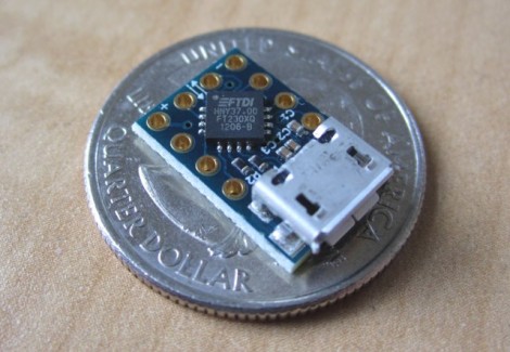
Using FTDI chips as a USB to Serial solution is nothing new, but this MicroFTX board takes the footprint to a new low. If you’re space limited this should have no problem fitting into your project. But if you plan to use it for prototyping we predict it’ll be lost in the parts bin forever as soon as you take your eyes off of it.

The USB Mini-B connector is becoming quite popular with hobby electronics these days. But here [Jim Paris] chose to use its little brother, the USB micro connector. Want to put this together by hand? How are you with 0402 footprints and QFN chips? In fact, there’s a ground pad on the bottom of that IC which means you really need to use a reflow oven to do the job right.

Aside from the diy-unfriendly fabrication size, we do like the design. There are four output pins (voltage, ground, TX, and RX) with a set of four solder jumpers to configure them. It can be powered from the USB port or an external connection, with the option for 5V or 3.3V output.

[Thanks John]

Going from idea to schematic to printed PCB

Building a circuit on a bread board makes life much easier, but eventually you’re going to want a PCB for one of your circuits. Luckily, [Will] from Revolt Lab put up a trio of posts that will take you idea and turn it into a schematic and PCB.

First up is an awesome tutorial on the circuit design program Fritzing. While you won’t find Fritzing on the computer of anyone making a living doing circuit design work – those people usually go for Eagle or KiCad – Fritzing is very easy to use but still has a ton of features. Using Fritzing isn’t very hard, either. [Will]’s tutorial goes over copying your breadboarded circuit into Fritzing, creating a schematic from the bread board layout, and finally converting that to PCB artwork.

Once you have board artwork for your circuit, you’re probably going to want a real-life PCB. [Will]’s board etching tutorial goes over the toner transfer method of PCB creation. Basically, print your circuit onto glossy photo paper with a laser printer, put it face down on a copper board, then take a clothes iron to it. If you’re lucky, the laser printer toner will have transferred to the copper making a nice etch resist. To get rid of all that superfluous copper, [Will] used ferric chloride but a Hydrochloric Acid/Hydrogen Peroxide mix will work just as well.

Before you etch your boards, you might want to thing about building an etch tank that keeps all your slightly dangerous chemicals in one container. [Will]’s etch tank uses a large water container and a few pieces of LEGO to suspend the board in the etch solution. It etches boards a lot faster than laying them face down in a tray, allowing you to go from idea to finished piece a lot quicker.

Flying microscope build seems way too nice for a home lab

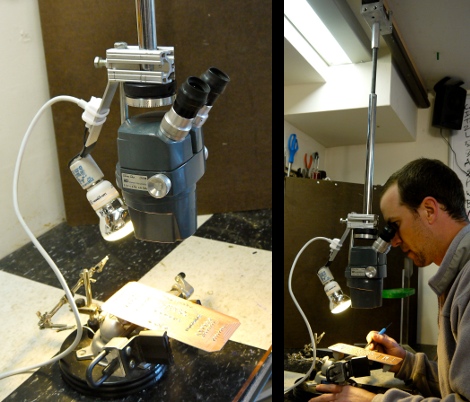
This flying microscope is a tool which [Darrell Taylor] can be very proud of. He wanted to have an inspection microscope for working with surface mount projects. He got his hands on a binocular version for a song and dance because it came without a stand. Initially he built a simple rig but if it wasn’t in the right place it was hard on the body, and the upright section was getting in the way of larger projects.

This time around he used a hanging track system instead of a stand. He had some aluminum track on hand which was originally meant for use with a sliding glass door. He fabricated a trolley to interface with the track, and added a vertical rod to support the microscope. This makes it easy to slide the unit to the side when not in use, and provides for some height adjustment as well. To add to the functionality he included a light on the opposite side of the scope. This keeps the project illuminated without shadows being cast by his hands or the scope itself.

Upgrading a digital multimeter to tell the temperature

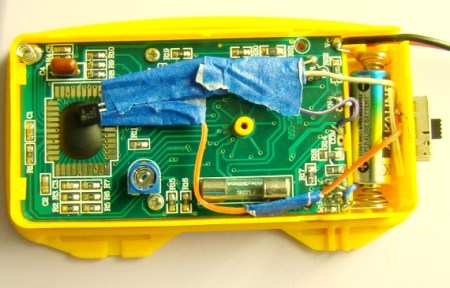
[Rajendra] tipped us off to this really slick hack he’s done to allow his multimeter to tell the ambient temperature. He’s basically measuring the output of an LM35 temp sensor that he has mounted in the case. The circuit is extremely simple and only requires the sensor, a couple resistors, and a switch so that you can return to normal function. When finished, you’ll have a multimeter that will display the ambient temperature when set to to the correct range (0-200 mV in his case). The switch is there so that you can return your multimeter to normal function afterwards.  While [Rajendra] chose to display ambient temperature, you could just as easily create an external probe for measuring other things.

Watch a shop tour through the screen of an oscilloscope

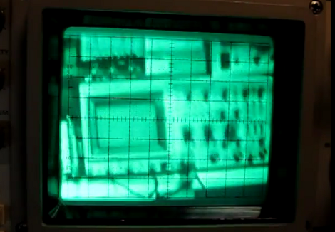
[Alan] posted a video tour of his electronics shop, but you’ll be viewing it through the green screen of an oscilloscope. The image above is a video camera filming a scope screen which displays the image of…. an oscilloscope (insert your own Yo Dawg meme here). But first he shares the technique he uses to display composite video on an oscilloscope screen.

The first three minutes of the video after the break are devoted to the video display hack. He starts with a glimpse of the breadboard circuit which takes the composite video signal and provides the necessary X, Y, and Z input signals to the scope to perform like this. He then walks through each portion of the schematic, which is based on an LM1881 video sync separator chip. The horizontal and vertical sync signals are separated by this chip, then filtered to produce ramp voltages for each to drive X and Y. The Z-axis is fed through a simple inverter circuit; Bob’s your uncle and your oscilloscope is now a TV monitor.

Of course this is not the first time this has been done. But we loved [Alan’s] presentation, and thought the shop tour was a fun way to finish off the video.

[Read more…]