Going from idea to schematic to printed PCB

Building a circuit on a bread board makes life much easier, but eventually you’re going to want a PCB for one of your circuits. Luckily, [Will] from Revolt Lab put up a trio of posts that will take you idea and turn it into a schematic and PCB.

First up is an awesome tutorial on the circuit design program Fritzing. While you won’t find Fritzing on the computer of anyone making a living doing circuit design work – those people usually go for Eagle or KiCad – Fritzing is very easy to use but still has a ton of features. Using Fritzing isn’t very hard, either. [Will]’s tutorial goes over copying your breadboarded circuit into Fritzing, creating a schematic from the bread board layout, and finally converting that to PCB artwork.

Once you have board artwork for your circuit, you’re probably going to want a real-life PCB. [Will]’s board etching tutorial goes over the toner transfer method of PCB creation. Basically, print your circuit onto glossy photo paper with a laser printer, put it face down on a copper board, then take a clothes iron to it. If you’re lucky, the laser printer toner will have transferred to the copper making a nice etch resist. To get rid of all that superfluous copper, [Will] used ferric chloride but a Hydrochloric Acid/Hydrogen Peroxide mix will work just as well.

Before you etch your boards, you might want to thing about building an etch tank that keeps all your slightly dangerous chemicals in one container. [Will]’s etch tank uses a large water container and a few pieces of LEGO to suspend the board in the etch solution. It etches boards a lot faster than laying them face down in a tray, allowing you to go from idea to finished piece a lot quicker.

Are your PCBs being tested as claimed?

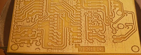
Florin ordered some PCBs from Iteadstudio, a pcb prototyping service. As part of their service, they claim that all PCBs are tested before they are delivered. However, many have been bringing this claim into question. [Florin] found a complete lack of any markings indicating actual probes had been used on his boards. Though they claim that 100% of the boards are e-tested, they replied to his inquiry somewhat cryptically.

All of the pcb’s have a stripe on the edge,it does not mean they have all been electrically tested ,it is the same as outline .

People on the Dangerous Prototypes Forum have been finding similar results. The company has commented, on this page, that that they will be responding to this soon (back in February)

Printing PCBs on a junked Epson printer

When it comes to making PCBs at home really quickly, there’s not much to improve upon with [Ryan]’s bodged up Epson printer that prints an etch mask directly on a piece of copper clad board.

Like most of the direct to copper PCB printer conversions we’ve covered ( 1, 2, 3 ), [Ryan]’s build relied on an Epson printer and Mis Pro yellow ink. The Mis Pro ink is one of the most etch-resistive substances that can be shot out of an inkjet printer, and Epson printer cartridges use a piezo pump that is perfect for squirting ink out on command.

After tearing the printer apart and lifting the print head a bit, [Ryan] needed a proper feed system to control where on the copper he was printing. He managed to make a board carrier out of a sheet of aluminum. By taping down the copper clad board, everything seems to work phenomenally.

After the break you can check out how fast [Ryan] can print out a fully etch-resisted PCB. It’s not improbable that he could produce a few dozen boards an hour; something our toner transfer PCB production method would kill for.

via makezine

[Read more…]

Adding a laser sight to your drill press in just a few easy steps

drill-press-laser-sight

[Derek] was using his Dremel drill press to prep a bunch of PCBs, and found that it was getting difficult to focus on the spinning drill bit each time to line it up with the solder pads on the boards. He figured that a laser sight would help move the process along, but since no off the shelf solution was available for his press, he built one of his own.

He bought a cheap desk lamp with a flexible metal neck, which he disassembled, saving the flexible metal sheath. He installed a conduit clamp on one end of the neck, and a laser module at the other. [Derek] then mounted the laser arm on the press’ crow’s nest aiming it at the tip of the drill bit.

As you can see in the video below, the ability to easily position the drill bit using the laser helps him make quick work of any PCB.

[Read more…]

All PCB quadcopter makes the most of each component

It’s difficult to contain our excitement for this tiny quadcopter project called the Picopter. [Frank] managed to pull together an impressive collection of features when developing the project. First off, the quadcopter itself uses all-PCB construction. Even the supports for the motors are PCBs with keyed slots to mate perpendicular to the main control board, then held firm with solder joints. We think this will be a more resilient option than this other all-PCB build.

The control board seen in the foreground has an edge connector which mates with a Wii classic controller connector. This is what you use for flight control. But there’s even more. The pinheader just visible on the left side of the controller mates with a socket on the ‘copter board. This allows you to sync the two so that there’s no radio frequency interference, and recharge the batteries from a USB connection. Speaking of those wireless communications, [Frank] chose to use an ATmega128RFA1. This is a newer microcontroller from Atmel that has a radio built into it. Add a gyroscope sensor and some motor control and you’re in business.

Don’t miss [Frank’s] video after the break when he explains all of the goodies found in his build. [Read more…]

384-LED ball receives animation wirelessly and knows its orientation

We get a ton of tips about Kickstarter projects. Here is a great example of what we need to see in order to feature one of them. This LED Blinky Ball developed by Null Space Labs is the target of a rather ambitious fundraising campaign. But in addition to the fundraising write-up they’ve shared extensive details about the prototype.

The ball is made up of sixteen slices; each is its own circuit board hosting an LED driver. All slices use the same PCB design, but one of them has an ATmega328 populated on the board to act as master. Optional components on the master board include an accelerometer, and a Bluetooth module to receive animation data. To get the full effect of the most recent prototype you’re going to want to see the video on their Kickstarter page.

Think this ball looks familiar to you? The original design was developed by [Nikolai] as a performance piece for a friend. This version was inspired by our feature of that earlier project.

So, use this as a template if you’re planning to submit your Kickstarter links to Hackaday’s tips line. We want to juicy details on the project!