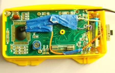
[Rajendra] tipped us off to this really slick hack he’s done to allow his multimeter to tell the ambient temperature. He’s basically measuring the output of an LM35 temp sensor that he has mounted in the case. The circuit is extremely simple and only requires the sensor, a couple resistors, and a switch so that you can return to normal function. When finished, you’ll have a multimeter that will display the ambient temperature when set to to the correct range (0-200 mV in his case). The switch is there so that you can return your multimeter to normal function afterwards. While [Rajendra] chose to display ambient temperature, you could just as easily create an external probe for measuring other things.


I like the simple idea behind this – adding more features to inexpensive DMMs.
I’ve been thinking about “smart” test harness design quite a bit lately.
The DMM gives you a good case, power, nice display, rugged inputs. You mostly need to condition the signals into an appropriate a/c, current, or dc voltage.
Another useful addition would be a way to export the data via a port, I2C, etc. Maybe an atmega and sdcard for logging.
There have been various kits to add ‘missing’ features to DMMs for years, temperature or current measurement was typical, I saw a lumens one once.
They work the same way this one does giving a reading on the volt scale.
They’re gone out of fashion these days as even a $20 meter will measure current, temperature, capacitance etc.
Current measurement as a kit? My $5 radioshack meter in the early 90s measured at least current, voltage and resistance.
Yep, even for current; though it was usually for accurate low current reading or a clamp to measure AC currents.
Something like this: http://tronixstuff.wordpress.com/2011/04/12/kit-review-current-clamp-meter-adaptor/. Apparently they still make ’em (or it’s old stock).
Is that masking tape?
I use it for EVERYTHING, better than electrical tape, but I use the white kind. It’s even better!
Blue masking tape- usually called “Painter’s tape”.
It’s basically expensive masking tape that comes up easier and is less likely to leave adhesive behind.
Yea, comes up easier, you don’t want that.
I use White masking tape for everything.
It’s just that it’s relatively flammable and not that well at spark isolation, and it sits next to the fuse and input traces all..
Also its glue is designed with the expectation that it won’t be used beyond a certain amount of time so many masking tapes have the glue either give out and/or harden and become brittle (and hard to remove I might add).
But if someone is happy with it it’s fine with me though.
Modifying your meter like this is dangerous if you plan to measure the likes of mains voltages. In this particular case, look how the look how the wire passes right next to the fuse!
That said, if you use a LM335Z then you can add a 10K calibration trimmer for spot-on readings – in deg. K of-course.
Finally, I wouldn’t hold the meter during measurements, body heat will tend to skew your readings.
Please! Where can I buy a $20 dollar meter that does NOT have all that junk on board. No temp, no frequency counter that goes to 2MHz, no bipolar TX tester of Hfe, no generator that goes to 2MHz, etc.
The fewer positions on the dial the better. Auto range only if it’s very fast. Ohms and volts next to each other with current at the end of the dial or at the bottom. VOmA.
The 1950s?
If you look at the battery, that’s a 12v one rather than the normal 9v, meaning he’s using a meter similar to this: http://www.multimeterwarehouse.com/DT830BMini.htm
They’re usually under $10 (occasionally $5!) but even they have transistor test. Aside from the probe-style ones, you won’t get much more basic than that (and probes are usually auto-range).
Daft!
How can it be modified to report temperature in Fahrenheit?
My version of this uses an HV850
and discrete multiplier to directy
read megohms ie insulation test.
Very handy, as you can also run
it at up to 10 kHz with reduced
output.
For those wanting to try this, I
strongly advise the use of 75V
output zeners on both HV8xx pins
and output resistors as it can
sometimes fry the chip if there
is an output short.