Pinball Stomp: Part 2

This is the 2nd and final part of this project. If you haven’t seen part 1 yet, jump back and check it out.

Now that we have the controller box made and ready to go, we just have to build some simple stomp sensors. As I said before, I doubt this will hold anyones attention longer than a night or two. With that in mind, I wanted to make this as cheaply and simply as possible.

To make these, you need the following:

  • Foam board or thick cardboard
  • aluminum tape
  • wire
  • duct tape

That’s it… no really, that’s it. Check out the video after the break to see how it all went, and what the kids thought of it.

[Read more…]

LED case lights reflect CPU usage

A lot of Linux users include system monitor information in their status panel so that they can see when the CPU is grinding away. [Kevin] is taking the concept one step further by changing his case lights based on CPU usage. Above you can see green, orange, and magenta, but [Kevin’s] implementation uses the full spectrum of color.

The project is based on an ATmega48. It’s running the V-USB stack and connects to one of the motherboard’s internal USB ports. This lets him easily push the CPU usage data over to the microcontroller where it is translated into color. One RGB LED has been installed behind each fan panel on the front of the case, with a white LED above and below as an accent. Pulse-width modulation via some MOSFETs lets him mix and match for just the right color. He’s powering the add-on off of the PSU rails rather than USB so that it turns off when the computer goes to standby.

Don’t miss [Kevin’s] explanation of the system, and a demo of it in action after the break.

[Read more…]

8-bit logic chip computer build

[Kyle] has been hard at working building an 8-bit computer from the ground up. He’s using a set of logic IC’s for the various components, and some NVRAM chips to store the control words. What you see above is the roadmap for his instruction set. He’s just started writing them to the chips, making the job easier by building an Arduino-based programmer.

We’ve enjoyed watching [Quinn Dunki’s] progress with her Z80  6502-based PC build which started on a breadboard in much the same way but has come a long way since those humble beginnings. Recently we also looked in on a 4-bit computer that is using discrete components. But [Kyle’s] take on the challenge falls somewhere in between the two.

The gist of his design can be found in one of his earlier post. He’s got a ring counter which starts by clearing the address register. It then loads the NVRAM address of the next instruction which is then executed on the subsequent count. It seems the build still has some way to go so make sure to keep your eye out for updates.

[via Reddit]

Building a computer with discrete transistors

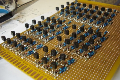
You’re going to want to do some stretching before undertaking a soldering project like this one. We’re betting that the physical toll of assembling this 4-bit discrete processor project is starting to drive [SV3ORA] just a bit crazy. This small piece of electronic real estate is playing host to 62 transistors so far, and he’s not done yet.

It’s one thing to build some logic gates in Minecraft (and then turn then into a huge 16-bit ALU). But it’s another thing to actually commit to a physical build. [SV3ORA] does a great job of showing the scope of the project by posting a tight shot of one inverter, then three in a row, then the entire 8-bit address and display system. These gates are built on the copper side of the board, with the power feed, LEDs for displays, and jumpers for control on the opposite side. We’re excited to see where he goes with this project!

But hey, if you don’t want to do that much soldering there’s a lot you can do on a few breadboards.

Real BMW dash cluster for your racing games

Here’s a cool add on that could making racing games just a little more engaging. How about a real instrument cluster? [Herctrap] has written up the schematics and shared the code to get a real car’s instrument cluster to be driven from x-sim. It is a slightly different approach than we’ve seen before, but really not too complicated.While this is still just another accessory sitting on his desk, it really seems to add a considerable amount of feedback to the game. Next he needs to build a motion rig for his seat!

[Read more…]

Veronica gets VRAM and its own boot logo

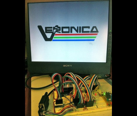
[Quinn Dunki] just reported in on the latest iteration in her computer project which is called Veronica. This time she added RAM to increase the VGA performance of her build. Like just about every other part of the project, [Quinn] knew what she wanted to do, but had to overcome a lot of issues along the way.

The goal is to implement a 256×240 display with 8-bit color depth. [Quinn] says this is on par with game console technology from the 1980’s. The problem is that the 10MHz AVR controller can’t really keep up with the scan rate of this size of display. The answer is to add RAM which stores all of the color data, the microcontroller will simply advance the address pointer on the memory chips to match the sync rate of the VGA output.

After hooking up her hardware design she gets a screen full of uninitialized pixel data. But moving from there to the final product seen above was quite frustrating. It turns out that noise on the breadboard was most of the problem, further compounded by entire breadboard row which wasn’t contacting the wires to make the temporary connections. A bit of jockeying for position and by Jove, she’s got a boot screen.

That breadboard sure has become crowded since her first VGA experiments.