Arduino compatible home automation for smart phone or voice control

[Joseph] wrote in to share this home automation system he’s working on as a college project. He calls it the Room Engine and the house-side of the hardware is built on top of the circuit you see here. This is the most basic part of the REBoard, which is meant to connect to a computer uses RS232 or USB, and in turn use a set of relays to switch mains voltage devices.

You can follow the bread crumb on his webpage to get a broader video of the system. The interface is designed to use two parts. One is a voice recognition system that is supported by the computer. The other is an iOS interface that includes login credentials and a button-based control system. The video after the break shows off the smart phone portion of the controller. We think he’s done a good job of integrating a few appliances without the need for commercial products such as X10 modules.

If you’re just interested in switching a few things without cord’s reach of each other this can get it done, and offers scheduling functionality. It would also be pretty easy to set this up with a WiFi module and do away with the PC.
[Read more…]

A much easier take on an Android garage door opener

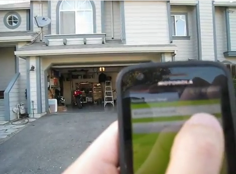
[Andy] is taking the complexity of a smartphone-controlled garage door down a notch with this project. He’s not interested in checking on the state of the door (open or closed) using a video feed, or in controlling the thing from anywhere in the world. He just wants to use his Android as the remote control and we say amen to that.

The circuitry in the garage is pretty simple. A relay is used to simulate a button press on the in-garage wired opener. This relay is driven by an Arduino which uses a Bluetooth shield for connectivity. Since his Android phone has a Bluetooth modem the rest of the project is just app development. As you can see in the video, the app automatically connects to the Arduino when it is launched, then waits for the button press to send the electronic equivalent of ‘Open Sesame”.

The project covers a series of posts so if you want to see how he got the app up and running make sure to browse through his archives. The next iteration for this app needs to be a background widget that enables Bluetooth, connects to the Arduino, and send s the open command all with one press.

[Read more…]

Turning a light off over the Internet

Because reaching over a few feet to turn off a switch is too much to bear for [Bruce], he connected his desk lamp to the Internet. It’s a pretty cool build that’s the perfect tutorial for connecting just about anything to the internet.

For his build, [Bruce] used an Arduino with a relay attached to an output pin. When the Arduino receives a signal on its serial port, a tiny voltage is applied to the relay, turning on the light.

This could have been done with an Arduino Ethernet, but the PHP script [Bruce] went with is a little more versatile. Whenever someone pulls up this digital light switch web page, they can turn [Bruce]’s desk lamp on and off.

For an introduction to connecting bare bones projects to the Internet, we’re really liking [Bruce]’s build. Just try no to go crazy with that link and leave the failure testing to the professionals. You can check out the demo video after the break.

[Read more…]

Simple tweak alerts you when you've left your headlights on

landrover-headlight-buzzer

[Paul McGuinness] owns a Series III Land Rover, and as the vehicle as formerly used by the British military, it’s lacking some of the modern amenities he was accustomed to. Overlooking the lack of power steering and all-around drum brakes, the one item that [Paul] really missed was a buzzer that let him know when he left the lights running.

On more than one occasion, he’s had to have “The Sarge” jump started after leaving the lights running all day. Explaining the humiliation involved with jump-starting a Land Rover with a Nissan Micra (an unfortunate excuse for a vehicle, known here in the states as the Nissan Versa) in his blog, [Paul] decided that he’d had enough – it was time to build a headlight warning buzzer.

The circuit itself is straightforward, consisting of a normally closed relay connected to his headlights and ignition, along with a buzzer. When the key is in the ignition and the lights are on, the relay is open and the buzzer is silent. However, if the lights are on and the relay is not supplied power from the ignition, it closes and sounds the alarm.

A simple fix for a frustrating problem – we like that.

Monitoring and controlling your garage door from afar with an IP camera

remote-control-garage-door

Last year, [Mark Simonelli’s] wife asked him if he could design something that would allow her to remotely check if their garage door had been left open. [Mark] jumped at the chance to tinker with electronics and designed a system around an old TrendNet IP camera. When remotely connected to the camera using IP Cam Viewer Pro for his Android phone, [Mark] could watch the video stream and also trigger the garage door opener via a small relay circuit he built.

His remote opener worked well, but his camera unfortunately lacked any sort of IR vision/low light capabilities. Since his camera wasn’t very useful in the dark, he decided that he needed to add some way to trigger a light when remotely monitoring his garage. He figured the best way to do this would be to control a power strip-connected light using a circuit similar to the one he built to open the garage door itself.

He stopped by the hardware store and picked up a cheap power strip, disassembling it and removing the power toggle once he got home. He fitted it with a small 5v relay, which he connected to the camera’s terminal block. While he admits that it might not be the absolute safest solution, he can easily control both the light and the garage door with a simple swipe of his phone’s screen.

Continue reading to see his remote controlled power strip in action, and be sure to swing by his site to see more details about his camera-controlled garage door opener.

[Read more…]

Auto power circuit for an arcade machine

Some of the pinball machines which [Jeri Ellsworth] has restored have ended up in the break room at her work. We’re sure her coworkers are thankful for this, but sometimes they forget to turn off the power to the machines, and letting them run constantly means more frequent servicing will be necessary. She set out to fix the situation by building a circuit that will automatically power the machines.

We think the solution adds some much needed functionality. Instead of hunting for the power switch, you can now power the machine up by hitting the left flipper, and it will automatically shut off after about five minutes of not having that flipper button pressed. For this she grabbed a 555 timer chip and built a circuit to control the relay switching the mains power.

She added a magnet and reed switch to the left flipper switch assembly to control her add-on circuit. It connects to the base of a PNP transistor which controls a resistor network and capacitor. This part of the circuit (seen to the left of the 555 in the schematic) allows the timer to be re-triggered. That is, every time you press the flipper the 555 will reset the timer. Don’t miss the demo she filmed after the break.

[Read more…]