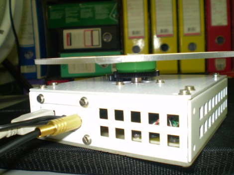
[Muris] has a friend who is selling items on the internet. This friend wanted a simple way to make rotating images of the products and asked him to help. The result of his labors is this base unit that drives the turn table and controls the camera.
The first iteration of the turntable was powered by the stepper motor from a floppy drive. A disc was mounted directly on the motor spindle, but the results were a bit poor. This is because the motor had a fairly low resolution of 200 steps per rotation. That doesn’t allow for smooth animation, and there was a lot of vibration in the system. An upgrade to the geared system you see above included swapping out that motor for one from an old scanner. Now it achieves 1200 steps per rotation and the vibration is gone.
The connectors seen in the base are USB, incoming power, and shutter control. [Muris] wrote a program to control the PIC 16F628A inside the base. The program sends commands via USB and has parameters for number of frames per rotation, direction of rotation, and the like. Set it up as desired, place the product on the turntable, and hit start. Unfortunately there’s no video of this in action because [Muris] gave it to his friend as soon as it was finished. We guess the fact that he didn’t get it back means it’s working great.
If you don’t mind some rough edges and exposed wiring you can throw a system of your own together pretty quickly.


Recent Comments