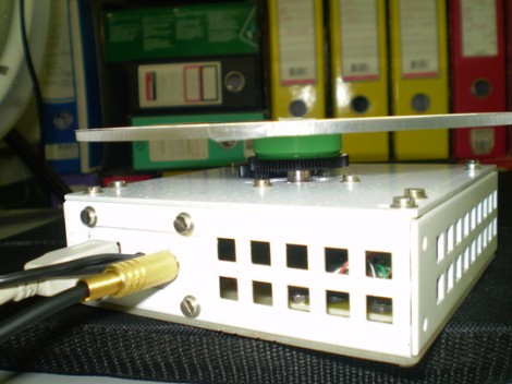
Automated turntable photography

[Muris] has a friend who is selling items on the internet. This friend wanted a simple way to make rotating images of the products and asked him to help. The result of his labors is this base unit that drives the turn table and controls the camera.

The first iteration of the turntable was powered by the stepper motor from a floppy drive. A disc was mounted directly on the motor spindle, but the results were a bit poor. This is because the motor had a fairly low resolution of 200 steps per rotation. That doesn’t allow for smooth animation, and there was a lot of vibration in the system. An upgrade to the geared system you see above included swapping out that motor for one from an old scanner. Now it achieves 1200 steps per rotation and the vibration is gone.

The connectors seen in the base are USB, incoming power, and shutter control. [Muris] wrote a program to control the PIC 16F628A inside the base. The program sends commands via USB and has parameters for number of frames per rotation, direction of rotation, and the like. Set it up as desired, place the product on the turntable, and hit start. Unfortunately there’s no video of this in action because [Muris] gave it to his friend as soon as it was finished. We guess the fact that he didn’t get it back means it’s working great.

If you don’t mind some rough edges and exposed wiring you can throw a system of your own together pretty quickly.

Hackaday Links: April 11, 2012

This hurts our head

You know you can ‘freeze’ drops of water in mid-air by flashing a LED at the right time, right? Well, according to this video you don’t even need a strobing light; just use the frame rate of the camera. Much cooler if you don’t know how it works, in our humble opinion.

Now do Junkyard Wars!

[James Cameron] and [Mark Burnett] (the guy who created Survivor) are bringing Battlebots back to the Discovery Channel. The new show is called Robogeddon and calls upon the current talent in the fighting robot world. Our prediction? Someone is going to build an amazing piece of art that will be completely destroyed in the first round; a wedge with wheels will take the championship.

A steam engine made out of rocks

[Hansmeevis] just spent 230 hours hand carving a steam engine out of gems. It’s called “Dragon’s Breath” and it’s an amazing piece of work: the cylinder is carved out of quartz, while the flywheel, mount, and base are carved out of jasper, onyx, zugalite, and other semi precious gems. Amazing artistry and it works.

Don’t lose a finger on all that science over there

[Dr. W] is a science teacher in Saint-Louis, France. Next year, his students will be learning about reaction propulsion and impulse conservation. To demonstrate these properties, [Dr. W] hacked up an old vacuum cleaner in to a jet engine and built a Pitot tube to measure the 140 km/h wind speed. Google translation.

Circuit bending a Sega Saturn

Making cool glitched-up graphics from Ataris and Nintendos is old hat, but not much has been done with circuit bending slightly more modern consoles. [big pauper] found his old Sega Saturn in his grandma’s attic and wondered what secrets this forgotten box held. It turns out he can make some pretty cool sounds and even cooler glitched out graphics. The pic above is from Virtua Fighter; done correctly these glitched low-polygon graphics could easily find themselves in a very stylistic indie game.

Experimenting with 8-bit graphics

[Vinod] has done a lot of work with microcontrollers, but this is his first try at displaying graphics using composite video. He had a small PAL television on hand, and an ATmega32 which just needs a stable clock source and a few resistors to get things going.

There are a lot of other hacks around that use composite video out with microcontrollers. But this is a ground-up approach which will help you understand the concepts behind these graphics. [Vinod] started by calculating the possible resolution. He needs to hold a frame buffer in memory, and since his chip has just 2 kilobytes of SRAM this will be the limiting factor. He settled on a display area of 128 by 64 pixels. This divides evenly by 8 so he’s not wasting any bits, and it totals 1k, leaving half of the SRAM for use in calculating the shapes which populate the buffer. An interrupt service routine runs ever 64 microseconds to feed data for each line of the display.

With the scanning in place, he moved on to fill the frame buffer. Two functions are used, one which sets a pixel the other clears a pixel. He compares these to using a pencil and an eraser. By calling these functions from his main program he is able to draw lines, boxes, and circles. A bit of creative looping and he’ll have animations as well, but that’s a concept for a different post.

Separating a working scanner from its broken printer

The laser printer portion of this all-in-one machine gave up the ghost and [Entropia] couldn’t get it working again. But the scanner was still functioning so he decided to separate the scanner from its dead printer module.

The model in question is a Samsung SCX-4200. The design is actually perfect for separation because the scanner sits on top of the out feed tray of the printer. It can even be lifted to allow more room for printed pages to pile up. All he has to do is separate the hinged connector and reroute the flat cables. But the real question in [Entropia’s] mind was whether or not the control board would work without the laser printer components connected to it.

He carefully disassembled the unit, spilling toner here and there which is left over from a catastrophic knock-off toner cartridge incident. A quick test showed him that although the drivers complain that the paper tray is open, the scanner does still work. He glued the controller board seen on the left to the bottom of the scanner enclosure, and added some felt feet. Now his scanner is closer to the size you’d expect. And on the plus side he gained a geared stepper motor, laser scanning unit, exhaust fan, and a couple of solenoids to use in future projects.

A six-year adventure into the world of CNC fabrication

Hackaday doesn’t always get the entire back story of a build. The usual assumption is that someone decided to build something, and with just a little bit of effort the project makes it into the Hackaday tip line. This doesn’t do justice to the builder, with skills honed after years of practice and experience. A 200-word summary is deceiving, and makes everything look almost too easy. [Michal] decided to buck that trend and sent in his half-decade long adventure of becoming one of the best micro-scale machinists we’ve ever seen.

In 2006, with years of robots made out of hot glue and cardboard behind him, and the quality of 3D printers not up to his exacting specifications, [Michal] snapped. He sunk the better part of $3000 into a Roland MDX-15 desktop mill. After several months of futzing about with acrylic sheet, [Michal] came across the wonderful machining properties of modeling board.

Determined to do something useful with this modeling board, [Michal] started looking into resin casting. Casting in resin is a common technique in the artist and model maker communities to mass produce small plastic parts. After getting his hands on eight liters of polyurethane resin, [Michal] made a useful part guiding the direction his skill set would grow in the coming years.

After years of experimenting with techniques, materials, and mediums, [Michal] eventually honed his craft and was able to finally start building real robots. These projects were a far cry from the cardboard and milk jug contraptions made earlier in his career. [Michal] was now producing incredibly precise gear assemblies with accuracies within 0.002 mm.

You may remember [Michal] from his robot with pivoting wheels we showcased last week. He got a lot of email from people wanting to know how to start delving into his unique blend of artistry, engineering, and craftsmanship. The good news is you can now learn from his mistakes, so a planetary gearbox shouldn’t take more than a few months to finish.

Simple tweak alerts you when you've left your headlights on

landrover-headlight-buzzer

[Paul McGuinness] owns a Series III Land Rover, and as the vehicle as formerly used by the British military, it’s lacking some of the modern amenities he was accustomed to. Overlooking the lack of power steering and all-around drum brakes, the one item that [Paul] really missed was a buzzer that let him know when he left the lights running.

On more than one occasion, he’s had to have “The Sarge” jump started after leaving the lights running all day. Explaining the humiliation involved with jump-starting a Land Rover with a Nissan Micra (an unfortunate excuse for a vehicle, known here in the states as the Nissan Versa) in his blog, [Paul] decided that he’d had enough – it was time to build a headlight warning buzzer.

The circuit itself is straightforward, consisting of a normally closed relay connected to his headlights and ignition, along with a buzzer. When the key is in the ignition and the lights are on, the relay is open and the buzzer is silent. However, if the lights are on and the relay is not supplied power from the ignition, it closes and sounds the alarm.

A simple fix for a frustrating problem – we like that.