Stair accent lights made from cheap LED strips

We really like [Geert’s] take on accent lighting for his stairs. He built his own LED channels which mount under the bullnose of each step. The LED strips that he used are actually quite inexpensive. They are RGB versions, but the pixels are not individually addressable. This means that instead of having drivers integrated into the strip (usually those use SPI for color data) this strip just has a power rail and three ground rails for the colors. Ten meters of the strip cost him under forty dollars.

He did want to be able to address each step separately, as well as mix and match colors, so he designed the driver board seen above to use a set of TLC5940 LED drivers. These are controlled by the Arduino which handles color changing and animations. It will eventually include sensors to affect the LEDs as you walk up the stairs. Each strip is mounted in a piece of angle bracket, and they’re connected back to the driver board using telephone extension wire.
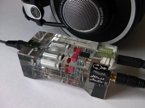
Free formed circuit protected by a brick of crystal clear resin

The look of this crystal clear resin brick is pretty amazing. [Rupert Hirst] decided to encase his amplifier circuit in a block of polyester resin. We just hope he got everything in his circuit right because there’s no way to replace any of those parts now!

He deserves a lot of credit for working out a visually pleasing way to mount each component. There wasn’t any type of substrate used, but a few lower gauge wires were picked as the rails and they add some mounting stability. Before casting, he took the case of each of the three jacks apart and sealed the seams with some of the casting resin to prevent the final pour from filling them up.

Eagle CAD was used to design the mold. He printed it out on some card stock, then used a hobby knife to cut the pieces out and super glue to assemble them. A second layer of super glue was run on each seam to ensure they’re water tight. After the casting was made [Rupert] spent plenty of time sanding, routing, and polishing the brick to achieve this look.

This makes us wonder about heat dissipation. Do you think it will be a problem? Tells us what your opinion by leaving a comment.

Add a train horn to your Hoopty (earplugs not included)

[TheChadster] was kind enough to explain that the air horn he attached to his bicycle is not actually as loud as a train horn. This one can only be heard from a half a mile away. But we’re sure the ringing in your ears will seem the same… the video after the break proves this thing is way too loud.

You don’t need much for this, just a pair of air horns and a source of compressed air. [Chad] has a ten gallon air tank strapped onto the luggage rack on the back. We’d bet he can lay on the horn for quite a while before depleting that reservoir. The hardest part of the build (other than sourcing the parts without breaking the bank) is going to be attaching everything to the bike. This is why he recommends using a cruiser bicycle because they often already have a rack on the back. For the horn holder [Chad] found a leather cup holder worked almost perfectly.

We think he needs to turn this around and add some compressed combustibles for a fiery and noisy flame boost.

[Read more…]

Arduino MIDI sequencer displays a lot of data

This Arduino MIDI sequencer has no shortage of ways to display loop info. The screen above is a touch-sensitive interface that acts as the user input. But if this screen is not visible, you can still see which tracks have activated samples for each beat and what effects are being used. That’s thanks to the collection of display boards which are shown in the video after the break.

The setup acts as the MIDI front end, relying on other hardware to generate the samples. It presents all of the options through several pages on the 320×240 touch screen display. The Ardunio Mega is responsible for monitoring the UI data, crafting and sending the MIDI commands, as well as updating the LED-based display boards. These include bar graphs for the various effects, a four row by sixteen pixel beat pattern display, and 7-segment displays to track the current location within the loop. All in that’s 368 LEDs driven by 18 shift registers.

Update: Link to a gallery can be found after the break as well.

[Read more…]

Using diodes and transistors as solar cells

When you get down to it, solar cells aren’t much different from the diodes and transistors in your parts drawers or inside your beloved electronics. They’re both made of silicon or some other semiconductor, and surprisingly can produce electricity in the presence of light. Here’s two semiconductors-as-solar panel projects that rolled into the tip line over the past few days.

[Steven Dufresne] cut open a 2N3055 power transistor to expose the semiconductor material to light. In full sunlight, he was able to produce 500 millivolts and 5.5 milliamps. In other words, he’d need around 5000 of these transistors wired up to turn on a compact fluorescent light bulb. A small calculator has a much lower power requirement, so after opening up five transistors he was able to make a solar-powered calculator with a handful of transistors.

[Sarang] was studying solar cells and realized a standard silicon diode is very similar; both are p-n junctions and the only real difference is the surface area. He connected a 1N4148 to a multimeter and to his surprise it worked. [Sarang] is able to get about 150 millivolts out of his diode with the help of a magnifying glass. While he doubts his diode is more efficient than a normal solar cell, he thinks it could be useful in low-cost, low power applications. We’re thinking this might be useful as a high-intensity light detector for a solar cooker or similar.

After the break, you can check out the videos [Steven] and [Sarang] put up demonstrating their solar cells.

[Read more…]

QArt codes, the better way to put picture in a QR code

[Russ Cox], current Googler and formerly of Bell Labs, posted an awesome guide to putting images in a QR code. Unlike this terrible attempt I wrote last August, [Russ]’s method does much more than simply paste an image into a QR code and hope the error correction passes. This new method generates a unique URL to be encoded for each QR code. In other words, the embedded image is actually part of the QR code and not just a copy and paste attempt.

The basis of [Russ]’ hack is the ability to change the message contained in a QR code to be made of either ASCII/UTF-8 or decimal numbers coded as binary. By appending an anchor tag (i.e. http://swtch.com/pjw/#123456789...) to the URL that will be encoded, [Russ] can change a whole bunch of pixels in a QR code to make just about any image.

With a few tricks like building new Reed-Solomon encoded blocks, [Russ] can change where in the pixels required by the QR code are placed. This allows for the full-width image of PJW’s binary likeness to be displayed in the QR code.

[Russ] put up a QArt coder that allows anyone to put a pixelated image in any QR code. [Luke Shumaker] (thanks for sending this in, [Luke]) took this tool and put the ‘ol skull ‘n wrenches inside a QR code pointing to hackaday.com. Very nice work from [Russ], and puts my work to shame. I’ll go cry in a corner now.