Reverse engineering a Futaba SBUS remote control

In the world of model aircraft, Futaba’s SBUS system is a big deal. Instead of having one servo per channel, the SBUS system allows for 16 proportional controls and two digital channels for each receiver. Basically, if you’re building an awesome plane with retracts on the landing gear and bomb bay doors, this is what you want to use. [Michael] wanted to use a few SBUS servos for a project he’s working on, so of course he had to reverse engineer this proprietary protocol.

Each SBUS servo operates over a single 100kbps serial connection with a few interesting twists: the signal is transmitted as big endian, but the individual bytes are little endian, something [Michael] figured out after stumbling across this month old mbed post. [Michael] used a serial library written by [fat16lib] and was able to change the parity and stop bits along with a simple hex inverter. Everything worked perfectly when the servo was connected to a an Arduino Mini.

Even though the SBUS system requires special Futaba servos, we can easily see how useful [Michael]’s work would be to outrageously complex robots or cnc machines. Check out the video after the break for a quick demo of [Michael]’s breadboard controlling one of these SBUS servos.

[Read more…]

Auto-locking pet door ensures that your outdoor kitty obeys its curfew

auto-locking-pet-door

If you’ve got a pet that roams freely in and out of your house, you may find yourself wanting to more closely regulate how they come and go. [tareker] was looking to keep his cat indoors at night when dangerous animals might be lurking in the neighborhood, but he didn’t want it to become a hassle.

He already had locking pet door on hand, which he hacked to regulate the egress and ingress of his cat automatically. He installed a pair of reed switches to determine if the door had been opened outwards (cat leaving) or inwards (cat returning), keeping track of the state using an Arduino Nano. A servo motor attached to the door’s frame locks the door whenever it detects the cat is safely inside after nightfall.

While he also added an RGB LED to reflect the status of the door, he’s considering connecting it to the Internet so that he can control and check the door from wherever he might be at the moment.

Wireless camera mount offers pan and tilt functions

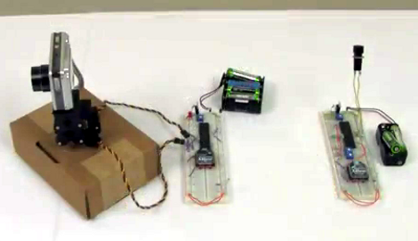
[Chris] put together a bunch of common components to create this wireless pan and tilt system for a security camera or a robot.

The motorized base is simple enough, using two servos to make up a mount for the digital camera. In this case he used a parts package which is designed to mount the servos perpendicular to each other. You could also 3D print, our build your own brackets quite easily. The control circuitry consists of a pair of PIC 18LF4520 microcontrollers and a set of Xbee modules. This is where the wireless connectivity comes in.

On the transmitter side, a pair of potentiometers are read by the microcontroller’s ADC and translated into position values. The receiver takes those values and drives the servo motors accordingly. In the clip after the break [Chris] is using micro trimpots which require a screw driver to adjust. You might want to hit the parts bin and see if you can get some that have a more user-friendly shaft or knob.

Unfortunately this system doesn’t transmit video. But WiFi webcams are getting quite affordable so that might be a good option in this case. [Read more…]

Sentry gun controller-board upgrade

This open source sentry gun controller board builds on a great concept by getting rid of the Arduino board. The previous version was an Arduino shield, but this upgrade keeps all of the cool features by rolling the necessary parts into one smaller footprint.

The image above doesn’t quite convey the scope of the project. Go take a look at the feature from last year which used the shield version of the controller. That build used a servo-mounted paintball gun in conjunction with a webcam. You can still build the same platform, but use the open-source files to include this board. It has outputs for three servo motors, and can also interface with airsoft or paintball guns which have their own electronic triggers and integrated batteries.

We always like to see the schematic for projects like this one. For your convenience we exported an image from the Eagle package. You can find it, along with the demo video, after the break.

[Read more…]

Glue Stick + Servo = Linear Actuator

glue stick linear actuator

What do you get when you cross a glue stick with a hobby servo motor? A linear actuator, of course! Although this could be done with other household implements, the form factor of this glue stick seems perfectly suited to sit on top of a servo horn.

The servo, as you might have guessed, has to be converted to rotate fully instead of the 180 degrees or so that is typical of these types of motors. The trick to this, and what really makes it shine in our eyes, is that instead of attaching two resistors in a normal continuous rotation mod, the potentiometer is used on the glue stick allowing for position feedback.

The resulting force from this gear-reduced actuator is quite impressive, giving an “err” (over 3 Kilograms) on the scale used for testing. [Gareth] or [Chiprobot] gives a great tutorial of how to make one of these after the break, but if you’d rather just see it in action, skip to around 8:20! [Read more…]

Increasing a digital servo motor's range of motion

Unhappy with the 120 degree range of movement for this digital servo motor [Malte] set out to expand its flexibility. He settled upon a hack that alters the feedback potentiometer in order to give the motor a wider range (translated).

The test video (embedded after the break) shows tick marks for before and after his alterations. You can see that the wider tick marks get much closer to the 180 degree range he’s interested in. The control method is no different than it was before, the internal circuitry is still listening for a control signal with pulses between 1 and 2ms to establish the position of the servo horn. [Malte] added resistors on the two outside legs of the feedback potentiometer. This is what that control circuit measures in order to judge the position of the servo horn. He’s using 1.6k Ohm resistors in this demonstration. But he didn’t just drop them in willy-nilly. His writeup discusses the calculations he used to determine the target voltage for the motor position he wants.

[Read more…]