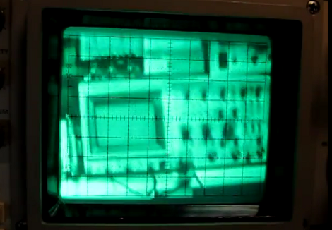
[Alan] posted a video tour of his electronics shop, but you’ll be viewing it through the green screen of an oscilloscope. The image above is a video camera filming a scope screen which displays the image of…. an oscilloscope (insert your own Yo Dawg meme here). But first he shares the technique he uses to display composite video on an oscilloscope screen.
The first three minutes of the video after the break are devoted to the video display hack. He starts with a glimpse of the breadboard circuit which takes the composite video signal and provides the necessary X, Y, and Z input signals to the scope to perform like this. He then walks through each portion of the schematic, which is based on an LM1881 video sync separator chip. The horizontal and vertical sync signals are separated by this chip, then filtered to produce ramp voltages for each to drive X and Y. The Z-axis is fed through a simple inverter circuit; Bob’s your uncle and your oscilloscope is now a TV monitor.
Of course this is not the first time this has been done. But we loved [Alan’s] presentation, and thought the shop tour was a fun way to finish off the video.


Recent Comments