Coin cell battery charger

[Jay Kickliter] built his own coin cell battery recharger. This won’t work on the vast majority of coin cells as they are manufactured as disposable parts. But there are rechargeable options out there with model numbers that start with LR instead of CR. In this case he tailored the charging circuit around MCP73832 IC and chose components best suited for charging his 110 mAh LR2450. But we believe all of the LR options out there are rated for 3.6V so altering his design for use with different models should be a breeze.

We’ve been unhappy with the use of disposable coin cell batteries for some time. Sure, in a real-time clock where the cell might last 6-8 years this is not very wasteful. But in an Apple TV remote that gets a lot of use, we hate the choice of a disposable battery. All of our less-hip remotes which use AA or AAA have NiMH rechargeables in them and have used the same pair for year and years. So we’re happy to see this charger project come along.

Now the bad news. We looked around and indeed you can find LR2032; a rechargeable replacement for the CR2032. But the capacity rating falls way flat. The model we looked at boasts only 50 mAh while the disposable CR2032 offers something along the lines of 240 mAh. Hopefully this will change as battery tech evolves.

Software defined radio from a USB TV capture card

With a simple digital TV USB capture card, you can build your own software defined radio or spectrum analyzer. While it may not be as cool as [Jeri Ellsworth]’s SDR, it’s still very useful and only requires $20 in hardware.

The only piece of hardware required for this build is a USB FM/DTV capture device with the Realtek RTL2832U chipset. So far, two USB sticks have been tested and the unit with the largest frequency range (64 – 1700 MHz) is available direct from China for $20.

Turning these cheap capture cards into software defined radios and spectrum analyzers was discovered by [Antti Palosaari] after sniffing the device. These cards demodulate the frequency and send all the data to the computer and is decoded via software. If you have one of these capture cards lying around, you can grab the software and load it up on your *nix box. Right now, the software only writes directly to a file, and may drop a few samples if writing to a hard disk instead of ram. Small problems, but we’re sure this project will pick up steam in the very near future.

via reddit

From reference design to USB sound card

[Entropia] decided to try his hand at rolling is own sound card. He picked out a DAC chip, started his prototyping by studying the reference design from the datasheet, then went through several iterations to arrive at this working model.

He chose to base the board around the PCM2706. It’s a digital to analog converter that has built-in USB support; perfect for his needs. It’s got a headphone amplifier, but is also capable of putting out S/PDIF signals for a digital amplifier to pick up and use. Not bad for a part that can be had for right around eight bucks.

The first PCB he designed had a few electrical and footprint errors. But he was able to get it to run by adding some point-to-point jumpers, and bending the legs of his capacitors to fit the board area. With those issued accounted for he ordered a second batch of boards. These went together nicely, but the headphone output was incredibly loud. Turns out the filtering circuit had the wrong resistor and capacitor values. Changing them around, and swapping the audio output so that the correct channels were patched to the audio jack brings it to the first release version seen above.

Build your own USB to Serial dongle

[Johan von Konow] found that he was using an FTDI USB-to-Serial chip in a lot of his projects and wanted to have an easy prototyping component on hand to facilitate this. What he came up with is the extremely small USB to serial dongle seen above. The copper fingers are designed to plug into your USB port. And if you’ve got an unused thumb drive (we’ve got a 128mb version that’s been collecting dust for years) it would make a perfect enclosure for the device.

He’s using an FT232BL chip in a LQFP-32 package. That’s got 0.8mm pitch so make sure you’ve got a steady hand, a fine tipped soldering iron, and some solder wick on hand. The 0603 passives might also give you a bit of a run-around during soldering, but all-in-all we think everyone will be able to successfully assemble this with a little bit of practice. The chip is the most expensive component at just under $6. But the good news is that the board is single sided and only needs one jumper wire making for very little drilling and easy home fabrication.

If you’re putting in a parts order, we’d recommend getting doubling the amount of resistors and capacitors. Chances are you’ll drop a few and nary will they be seen again. We also highly recommend looking into [Gerrit’s] surface mount component clamp.

Reverse engineering an oscilloscope circumvents vendor crippleware

oscope-reverse-engineering

The crew over at the Hungarian Autonomous Center for Knowledge (H.A.C.K.) say they aren’t the most well-funded organization out there, so they were stoked when they found they could afford to bring a slightly used UNI-T UT2025B digital oscilloscope into the shop. As they started to tinker with it, the scope revealed one major shortcoming – screenshots were only accessible via a USB connection to a Windows computer.

Since they didn’t have any Windows boxes in house, [András Veres-Szentkirályi] decided he would try reverse-engineering the protocol so they could get access to this useful feature.

He set up a Windows VM, and using Wireshark on the host Linux box, [András] sniffed the data passing over the scope’s USB interface. He was able to identify what looked like image packets being sent to the VM, which he was able to decode using a small Python script. The resultant images were monochrome and they didn’t look quite right, but it was a start. As he dug further [András] found that he was overlooking some of the color data packed into the images, and after a bit of fiddling he got the sharp, colorful image you see above.

It turns out that while the scope has a monochrome LCD, it sends 16-bit color images over the USB interface – images that the Windows’ client degrades before displaying them on the screen. So in the end, he was not only able to get the scope working on any OS with the ability to run Python, he was able to grab far better images than the manufacturer ever intended – A very nice hack if we do say so.

Be sure to swing by the H.A.C.K. wiki as well as the project’s github repository if you have one of these scopes and are looking to wring some better images out of the hardware.

USB slingshot controller is for the birds

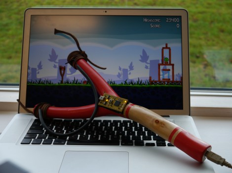
This USB slingshot controller really brought a smile to our faces. Part of it is the delightfully silly promo video you’ll find after the break. [Simon Ford] combined nature and technology to bring this USB-enabled slingshot into existence.

The frame itself is from a branch he found in the Epping Forrest of London. He whittled away the bark, and hollowed out an opening in at the base of the ‘Y’ to receive an accelerometer board. It has a pair of female pin headers to interface with the mbed seen in the image above. But the real hack here is the code he wrote to translate accelerometer data into appropriate mouse movements. His success in the area makes this translate the virtual world of Angry Birds in a visceral experience of killing things with a slingshot.

We’re suckers for this type of project. Two examples that pop into mind are these musical instrument hacks for Rock Band 2.

[Read more…]