Conway's Game of Life in HD

We’re going to have to take [Mike’s] word for it that he built Conway’s Game of Life with high-definition video output. That’s because this screenshot is his only proof and it looks a bit fuzzy to us. But we are interested in the project which used an FPGA to generate a 1080p VGA output of the classic programming challenge.

One of the biggest benefits of using an FPGA for this application is the hardware’s parallel processing ability. For every frame of the game, the area around each living cell must be analyzed to produce the next evolutionary step. Most of the time this means processing all of the pixels in the playing area, which is the case here. [Mike] is using VHDL to program a Papilio Plus which has a Spartan 6 chip on it. He separated his code into the different components when writing about it. This makes it easy to find the chunks relating to the game if that’s what you’re interested in. If you just want to see how he implemented the VGA interface that’s well documented as well.

If you’re not familiar, Conway’s Game of Life has simple rules regarding when a cell will live, die, or be reborn. As [Mike] points out, every programmer should give it a shot at some point. We’ve seen many iterations from the very large to the very small.

Experimenting with 8-bit graphics

[Vinod] has done a lot of work with microcontrollers, but this is his first try at displaying graphics using composite video. He had a small PAL television on hand, and an ATmega32 which just needs a stable clock source and a few resistors to get things going.

There are a lot of other hacks around that use composite video out with microcontrollers. But this is a ground-up approach which will help you understand the concepts behind these graphics. [Vinod] started by calculating the possible resolution. He needs to hold a frame buffer in memory, and since his chip has just 2 kilobytes of SRAM this will be the limiting factor. He settled on a display area of 128 by 64 pixels. This divides evenly by 8 so he’s not wasting any bits, and it totals 1k, leaving half of the SRAM for use in calculating the shapes which populate the buffer. An interrupt service routine runs ever 64 microseconds to feed data for each line of the display.

With the scanning in place, he moved on to fill the frame buffer. Two functions are used, one which sets a pixel the other clears a pixel. He compares these to using a pencil and an eraser. By calling these functions from his main program he is able to draw lines, boxes, and circles. A bit of creative looping and he’ll have animations as well, but that’s a concept for a different post.

V-Synch detector lets you use 3D shutter glasses on Linux systems

This circuit is how [John Tsiombikas] makes his cheap 3D shutter glasses work with a Linux machine. It’s not that they were incompatible with Linux. The issue is that only certain video cards have the stereo port necessary to drive the head-mounted hardware.

Shutter glasses block light from one eye at a time, so that different renderings can be shown to create the stereoscopic effect. Since stimulating the muscles in the eye doesn’t actually work, you need to find a way to drive the glasses in perfect time with the video signal. His circuit watches for the V-Sync signal, then uses it to toggle the shutter glasses. Since the hardware has no way of knowing whether the left or right frame is being generated, he included the toggle switch as a user-controlled adjustment. If the 3D isn’t coming together, you’re probably viewing the frames with the wrong eye and need to flip the switch.

There’s really no way to show the effect without trying out the hardware in person. But [John] reports that it works like a charm when used with the OpenGL stereo wrapper.

Digital gaming table made with no smoke, just a mirror

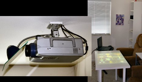
The concept of having a digital gaming table got stuck in [RobotGuy’s] mind over the weekend and he managed to whip this up in no time using materials on hand. He already had a ceiling-mounted projector which just happens to reside immediately above the space occupied by his coffee table. By swapping that piece of furniture out for a white Ikea table, and adding a mirror to the projector he now has the virtual gaming surface he was looking for. The mirror mount is nothing more than a desk lamp that includes a spring clamp and flexible neck. He hot glued the piece of mirror to this, and attached it to the projector’s ceiling anchor. Since rear-projection screens are common, all digital projectors have the ability to mirror and rotate the image being displayed so that it appears on the table in the correct orientation.

We love the look, but this is really only one portion of a digital gaming project. We think the table needs some interactivity. We often see this done using infrared light processed by a webcam. That multi-touch option is not going to work with a standard table since the camera needs to be on the opposite side of a translucent surface. But if you don’t mind using a stylus this IR whiteboard technique would work.

Burning plasma screen with breathtaking beauty

image

At some point you’ve got to resign yourself to the fact that the TV you’ve been trying to resurrect is just not salvageable. But if you’re knowlegable about working safely with high voltage, you might get quite a show out of it yet. Here [Aussie50] finds beauty in destruction when he fries a large plasma panel from a broken HDTV.

The flyback transformer from a microwave oven drives the display. The video after the break starts off kind of boring at first but before long it takes off. As portions of the display burn out the electric arcs jumping those gaps provide a thrilling view for the remainder of the 14 minutes.

Don’t want to commit to a video that long? Here’s a display that gives up the ghost after just four and a half minutes but we don’t think it’s quite as cool.

[Read more…]

ATmega324 acts as a GPU for homebrew computer

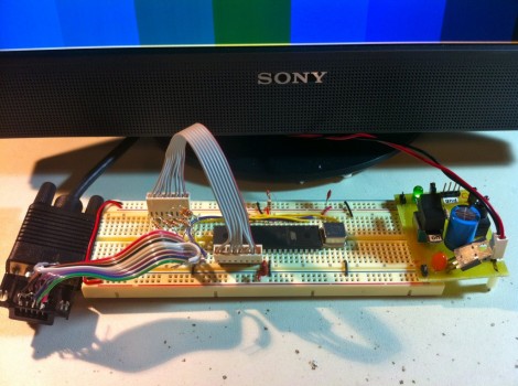
[Quinn Dunki’s] homebrew computer project is moving up another evolutionary rung. She needs a more versatile user interface and this starts with the data output. Up to this point a set of 7-segment digits has served as a way to display register values. But her current work is aimed at adding VGA output to the system.

She starts off her write up by justifying the protocol choice. Although composite video would be easier to get up and running (we see it in a lot of AVR projects) [Quinn] doesn’t have a screen that will display composite video. But there’s also a lot of info out there about VGA signal generation. She delved into the specifics and even found a great AVR-based example over at Lucid Science.

The version seen above uses the 40-pin ATmega324. It’s a lot bigger than necessary for the example she put together, but in the future she plans to add video memory and will be glad to have all of those extra I/O pins. When it comes to video sync, timing is everything. She wrote the code to drive the display using assembly. In this way, she was able to look up the cycles used for each command to ensure that the loop is running with near perfect timing.