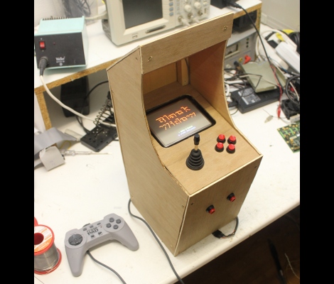
CRT vector graphics arcade game built from an FPGA board

[Sprite_TM] wanted to challenge his VHDL skills, and there’s no more satisfying way of doing this than making something that will be playable when you’re done. He decided to try his hand at creating a vector-based CRT arcade. The distinction here is that vector-based games take control of the magnetic ring that guides the electron path toward the screen. This technique allows point-to-point graphic generation rather than the pixel-based scanning that CRT televisions use.

He had a small color CRT on hand and decided to grab a VHDL version of asteroids from the Internet to see if he could get it to work. But upon further inspection of the source he found that it had a chunk of code which rasterized the vectors for use with a scanning monitor. After removing that chunk, and giving it a spin he had enough confidence that he knew what he was doing to start implementing his own game. The choice of what title really came down to the hardware the original arcade cabinets used. He was not interested in implementing a soft-process for the math chips used in games like Star Wars and Tempest. In the end he got a version of Black Widow up and running, and even built a miniature cabinet for the thing. Check out some of the gameplay in the clip after the break.

[Read more…]

Auto power circuit for an arcade machine

Some of the pinball machines which [Jeri Ellsworth] has restored have ended up in the break room at her work. We’re sure her coworkers are thankful for this, but sometimes they forget to turn off the power to the machines, and letting them run constantly means more frequent servicing will be necessary. She set out to fix the situation by building a circuit that will automatically power the machines.

We think the solution adds some much needed functionality. Instead of hunting for the power switch, you can now power the machine up by hitting the left flipper, and it will automatically shut off after about five minutes of not having that flipper button pressed. For this she grabbed a 555 timer chip and built a circuit to control the relay switching the mains power.

She added a magnet and reed switch to the left flipper switch assembly to control her add-on circuit. It connects to the base of a PNP transistor which controls a resistor network and capacitor. This part of the circuit (seen to the left of the 555 in the schematic) allows the timer to be re-triggered. That is, every time you press the flipper the 555 will reset the timer. Don’t miss the demo she filmed after the break.

[Read more…]