CNC'd business cards will definitely get you noticed

cnc-business-card

The guys over at North Street Labs were bored, so they figured why not go ahead and built a CNC machine just for kicks. While they haven’t put up build details on the CNC just yet, they do have some newly milled business cards to show off just how well the machine works.

Part ruler, part LED throwie, we think their new business cards look great. Milled out of thin acrylic sheeting, their cards feature the North Street Labs logo and URL along with 1/32” ruler markings along the top. The card is also fitted with space for a button cell battery and RGB LED, which illuminates the entire card nicely from the side.

They say that the cards take about 5 minutes apiece to make, which is not bad at all. At $0.50 a pop, the cards are not nearly as cheap as those made from cardstock, but when you’re looking to impress what’s a couple of quarters?

Continue reading to see a short video of their CNC-milled business cards in action.
[Read more…]

The best LED cube build we've seen

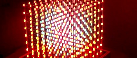
[Nick] wrote in telling us about the LED cube he built over the course of six months. He calls LED cubes ‘done to death,’ but [Nick] might be too humble. His 8x8x8 RGB LED cube is the best we’ve ever seen.

To start his build, [Nick] built a simple 4x4x4 cube as a proof of concept. The baby cube worked but the fabrication process got him thinking. Instead of building his monster LED cube in layers from the bottom up, he would need to build columns from left to right. After the construction of a jig, soldering eight panels of 64 LEDs, and buying a new soldering iron tip, [Nick] had a beautiful assembled LED cube. The only thing missing was the electronics.

Most of the LED cubes we’ve seen use the TLC5940 LED driver for hardware PWM, [Nick] decided to go with the simpler but more familiar STP16 chip. After hooking up his huge LED driver board up to a chipKIT Uno, the 80 hours of programming began.

In the end, [Nick] built the best LED cube we’ve seen (even though it isn’t the largest) and put together one of the best build logs in recent memory. Because no LED cube build is complete with out a video there’s an awesome demo after the break.

[Read more…]

Digital speedometer with an arduino

[Martyn] is restoring a 32-year-old Honda motorcycle, so when the ancient speedometer broke last year he thought it was prime time to start of a digital speedometer project. We’re loving the results so far, and would love seeing it on a nicely restored bike.

Instead of the relative horror of driving 40 LEDs with a single Arduino, [Martyn] bit the bullet and got a Maxim 7221 LED driver. Controlling 64 LEDs  over a three-wire interface simplified the board design somewhat, allowing [Martyn] to etch his own PCB with the toner transfer & HCl/H2O2 method. To actually power and control the entire circuit, [Martyn] used an Arduino loaded up with a program based  LedControl library makes programming the spedometer a snap.

Although the speedo works, [Martyn] says he isn’t proud of how it looks. We don’t mind – the candy colored jumpers add a nice flair to the project, and they’re hidden behind the face plate of the speedometer. We’re sure once he gets the neutral, high-beam, and warning indicators working with the LED bar array / tachometer, everything will look awesome.

via reddit

Display made out of hundreds of seven segment LEDs

While huge LED panels are a relatively common project du jour for people wanting to flex their engineering muscle, we’re taken aback by the sheer beauty of [Skot9000]’s huge LED display made of seven-segment displays. He calls the build DigitGrid, and it’s a wondrous display the likes of which we’ve never seen.

To build a display based on seven-segment LEDs, [Skot] went with a modular approach in designing the DigitGrid. To power and control all these seven-segment displays, [Skot] used a Texas Instruments TLC5920 to run four 4-digit displays as a single module. Four of these modules connect together to form a row of 32×2 digits, and eight rows of digits come together to make a 512-digit display. With seven LEDs for each digit, that works out to 3,584 4,096 individual LEDs for the entire panel.

To power and control this gigantic array of LED displays, each row uses a PIC16F microcontroller which, in turn, is controlled by an FPGA. After several hours of writing Verilog, [Skot] had a reasonably good hunk of software that allowed him to send frames from his computer to the display. The results, quite simply, are amazing. [Skot] managed to put up a short film showing off the animation capabilities of his new display, and it’s a wonder to behold. You can check that video out after the break.

[Read more…]

Tearing down a failed LED bulb

todd-harrison-led-bulb

[Todd Harrison] was thinking of replacing some incandescent light bulbs in his house with LED models, so and his wife picked up a single candelabra bulb to test before they spent the cash to swap them all out. The bulb died in about a week’s time, so [Todd] got out his trusty electronic disassembly device (his hammer), sharing his post-mortem examination with us.

After taking a cursory look at it, [Todd] found that the circuit powering the bulb was not overly complicated. A small bridge rectifier along with a few caps and resistors are all that was used to power the device, making it’s failure a bit puzzling. When [Todd] wired it up to his power supply, the bulb lit up, much to his surprise. His best guess as to why it died is that the shrink wrap around the PCB managed to cause a short, though he also noticed that one of the bridge rectifier’s legs was not soldered down.

He started tooling with the light to find out more about it, but he managed to blow out a handful of LEDs in the process. All in all the LED lighting swap was a disappointment, but at least he had some fun along the way!

Continue reading if you’re interested in seeing [Todd’s] diagnosis in its entirety.

[Read more…]

USB controlled SPÖKA night light

usb-controlled-spoka-nightlight

[wejp] picked up an IKEA SPÖKA night light, but he wasn’t entirely impressed with its functionality. Pressing the top of the ghost’s head causes it to cycle through a few colors, and pressing it a second time locks it into displaying the current color until its tapped again. Inspired by this SPÖKA hack which used a different version of the night light, he tore his down to see what he could do with it.

Upon stripping off the outer cover, he found that the internals were considerably different than those found in its glowing brethren, though they were perfect for what [wejp] had in mind. He removed the rechargeable battery pack as well as the controller board, which sits on a PCB separate from the LEDs. He replaced the stock micro with an ATtiny25, which he uses to give himself a bit more control over the light display.

He couldn’t quite cram all the functionality he desired into the ATtiny, but he planned on powering the light using his computer anyhow, so he installed a small USB port in the back. When connected to his PC, the SPÖKA can be controlled more precisely than when it operates alone.

Unfortunately there’s no video available of the SPÖKA light in action, but there are plenty of images available on his site.