Board lets you know when to hold 'em; know when to fold 'em

Don’t mind me, I’m just listening to some tunes during our poker game. Well, that and getting some electronic coaching about poker odds. This board lets you wiggle your toes to input the upcards, and those in your hand. After each entry the gadget will tell you your odds of winning the hand. Take it easy with this kind of stuff, if Rounders was at all realistic, getting caught cheating is a painful mistake.

The thing we find interesting about the system is that it doesn’t use a stored odds database. Instead, the Propeller chip runs a simulation of 1000 hands of poker based on the cards you have entered and uses the results to calculate the odds. [Nick] says that this runs quickly because he’s using multiple cores for the calculations, and it cuts down on the data that the device needs to have on board. Right now the feedback uses a text-to-speech generated voice, but you can customize the audio clips if you’d like. Check out a demo of the device in the clip after the break.

Not looking to get the beat down for cheating? Here’s a poker tournament timer that we assure you is on the up-and-up. [Read more…]

Experimenting with 8-bit graphics

[Vinod] has done a lot of work with microcontrollers, but this is his first try at displaying graphics using composite video. He had a small PAL television on hand, and an ATmega32 which just needs a stable clock source and a few resistors to get things going.

There are a lot of other hacks around that use composite video out with microcontrollers. But this is a ground-up approach which will help you understand the concepts behind these graphics. [Vinod] started by calculating the possible resolution. He needs to hold a frame buffer in memory, and since his chip has just 2 kilobytes of SRAM this will be the limiting factor. He settled on a display area of 128 by 64 pixels. This divides evenly by 8 so he’s not wasting any bits, and it totals 1k, leaving half of the SRAM for use in calculating the shapes which populate the buffer. An interrupt service routine runs ever 64 microseconds to feed data for each line of the display.

With the scanning in place, he moved on to fill the frame buffer. Two functions are used, one which sets a pixel the other clears a pixel. He compares these to using a pencil and an eraser. By calling these functions from his main program he is able to draw lines, boxes, and circles. A bit of creative looping and he’ll have animations as well, but that’s a concept for a different post.

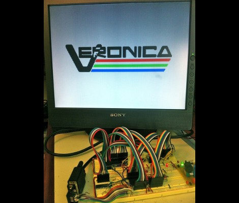
Veronica gets VRAM and its own boot logo

[Quinn Dunki] just reported in on the latest iteration in her computer project which is called Veronica. This time she added RAM to increase the VGA performance of her build. Like just about every other part of the project, [Quinn] knew what she wanted to do, but had to overcome a lot of issues along the way.

The goal is to implement a 256×240 display with 8-bit color depth. [Quinn] says this is on par with game console technology from the 1980’s. The problem is that the 10MHz AVR controller can’t really keep up with the scan rate of this size of display. The answer is to add RAM which stores all of the color data, the microcontroller will simply advance the address pointer on the memory chips to match the sync rate of the VGA output.

After hooking up her hardware design she gets a screen full of uninitialized pixel data. But moving from there to the final product seen above was quite frustrating. It turns out that noise on the breadboard was most of the problem, further compounded by entire breadboard row which wasn’t contacting the wires to make the temporary connections. A bit of jockeying for position and by Jove, she’s got a boot screen.

That breadboard sure has become crowded since her first VGA experiments.

Resizable ARM dev board; just take some off the top

[Bob Alexander’s] most recent project is a hack saw resizable ARM breakout board. He wanted to start using more ARM microcontrollers in his projects and went for a breadboard friendly design. It uses a 40-pin dip package, but if you need the horsepower but not the I/O you can literally cut it down to size. We might recommend grabbing some tin snips, which can cut through a PCB like butter, but to each his own.

The board is based around an STM32 chip. You’ll find a crystal oscillator for the system clock, and a clock crystal if you need it. On the other side of the chip he included a footprint for a voltage regulator. This setup provides a remarkable range of input voltages, accepting from 2 to 3.6 volts without the regulator, and up to 16 volts if the regulator is present. He designed a package footprint that can be easily bridged if there’s no SMD part there. Just make sure you insulate that pad if you are using one with a conductor on the bottom. He explains this in detail in his writeup.

You’ll need a programmer to work with the board. He uses an STM32 Discovery Board for this but there are quite a few other options out there too.

Apartment entry morse-code lock

[Bozar88] lives in an apartment building that has a buzzer at the front security door. Guests find your name on the panel next to that door, and press a button to ring the phone just inside the entry of each apartment unit. He decided to extend the built-in capabilities by adding a morse-code entry password which unlocks the security entrance automatically (translated).

He designed a circuit and etched his own board which fits nicely inside of the wall-mounted phone. It uses an ATtiny2313 to implement the coding functions. The device attaches to the intercom line in order to detect incoming button presses from the entry panel. There’s some protection here to keep the signal at or below 5V. The output is two-fold. The microcontroller can drive the microphone line using a transistor, which gives the user audio feedback when the code is entered. To unlock the door an opt-isolated triac (all in one package) makes the connection to actuate the electronic strike on the entry door.

The video after the break is not in English, but it’s still quite easy to understand what is being demonstrated.

[Read more…]

Building a media player with an MSP430

A media player based on an Arduino and SD card has been done to death several times over, but that doesn’t mean we can’t appreciate [Matt]’s MSP430 audio player. It’s a very nice piece of work that supports a FAT16 file system and only takes up 54 bytes of RAM.

To make his dream of a 430 media player a reality, [Matt] based his work on the DIY Life Talking MSP430 project. Unlike this previous attempt to play music with a ‘430 and SD card, [Matt] threw in a full FAT16 file system, allowing him to drag and drop audio files on his computer to the SD card.

Right now [Matt]’s build can play a stereo audio file through its speakers, but the sound quality over a mono file is greatly reduced. The maximum sample rate is 16kHz; a ‘good enough’ sample rate if you’re listening with terrible headphones. In the video after the break, [Matt] plays this awesome Symphony of Science on his homebrew media player. We’re guessing his camera doesn’t do his project justice, but it’s still impressive nonetheless.

[Read more…]